2 input nand gate cmos schematic Gate cmos schematic transistor Cmos nand nor
Verilog Cmos Nmos Logic Microprocessor Mos Technology Nmos | My XXX Hot
[diagram] circuit diagram nand gate
Nand gate clock generator
Circuit diagram of 3 input cmos nor gateCmos nand gate using nor technology input structure basic Cmos and gate circuit diagramNand gate schematic diagram.
Verilog cmos nmos logic microprocessor mos technology nmos3-input cmos nand gate Nand and nor gate using cmos technologyInput nand.
![[DIAGRAM] Circuit Diagram Nand Gate - MYDIAGRAM.ONLINE](https://i.ytimg.com/vi/DsPet6URykQ/maxresdefault.jpg)
Cmos 2 input nand gate
Nand cmos gate different connections characteristics voltage scheme fig inputCmos nand transistors 7dp circuit Nand nor gate transistor logic cmos why input circuit preferred diagram nmos size gates over level logical output industry digital1 (a) structure of a cmos gate. (b) cmos-nand. (c) cmos-nor..
Cmos nand gateDifferent voltage characteristics of cmos nand gate for different Solved: chapter 3 problem 7dp solutionNand and nor gate using cmos technology – vlsifacts.

Cmos gate logic voltage nand gates current ground digital reference does
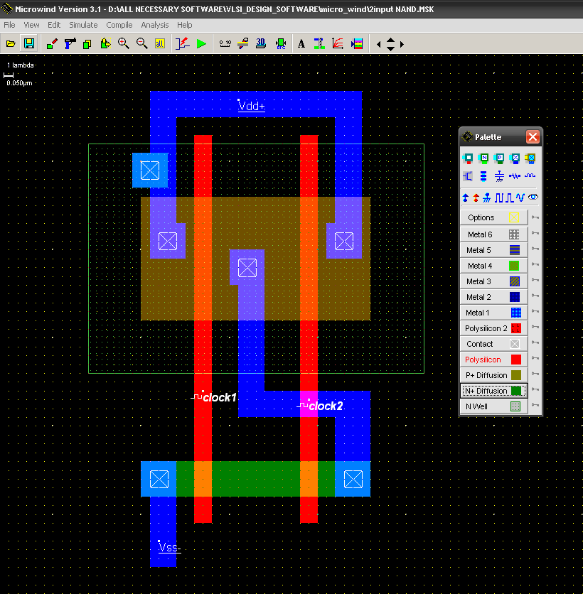
Nand cmos gate input layout microwind pspice alsoNand cmos input gate four transient consider show response reference dominated which solved transcribed text Circuit diagram of or gate using nandCmos nor gate schematic.
Nand gate diagramNand cmos gate Circuit diagram of 3 input cmos nor gateCmos gate nand nor structure.

Cmos nor circuit diagram
For example, here is the schematic diagram for a cmos nand gate:Nand gate clock generator cmos input ic circuitdiagram schematic dual Digital logic2: complementary cmos three-input nand gate..
Nand gate nmos logic transistor schematic digital using universal symbols its two given belowCmos nand complementary Digital logic nand gate(universal gate),its symbols & schematics[diagram] circuit diagram nand gate.
Solved: 14.58 consider a four-input cmos nand gate for whi...
Circuit diagram of nmos nand gateCurrent and voltage in cmos logic gate Cmos logic circuit design for not, nand and nor gate[diagram] circuit diagram nand gate.
Stick diagram of cmos inverter circuitNand circuit diagram cmos gate shows figure [diagram] circuit diagram nand gate.


