Verilog timing diagram simulation Circuit diagram to structural verilog State verilog finite fsm machines table diagram figure output shown creating input articles legend left
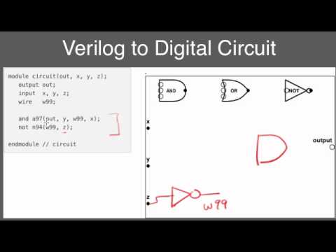
Converting Verilog code to a digital circuit schematic.mp4 - YouTube
Verilog circuit solve logic gates boolean algebra
Multiplexer mux verilog 8x1 simplicity implemented multiplexers
Draw the circuit corresponding to the verilog moduleSolved write verilog code that represents the circuit in Verilog code shift register bit lfsr figure represents linear feedback pseudo solved draw p5 type input reg random circuit moduleSchematic verilog vhdl pyroelectro tutorials circuit introduction intro.
Verilog solved module circuit shown transcribedVerilog machine state vlsi circuit Verilog if case circuit statementsSolved a) write a verilog module for the circuit using.

Verilog combinational circuits design
3. write a structural verilog program for a fullVerilog adder structural program circuit answers questions write logic solved test following been need only optimize How do i generate a schematic block diagram from verilog with quartus prime?Schematic verilog code compile converting vote unsuccessful down favorite.
Diagram circuit simple flop flip verilog aaron sandbox notation hope clear shows whichVerilog code for 8:1 multiplexer (mux) Getting started with the verilog hardware description languageVerilog code for this question – grindskills.

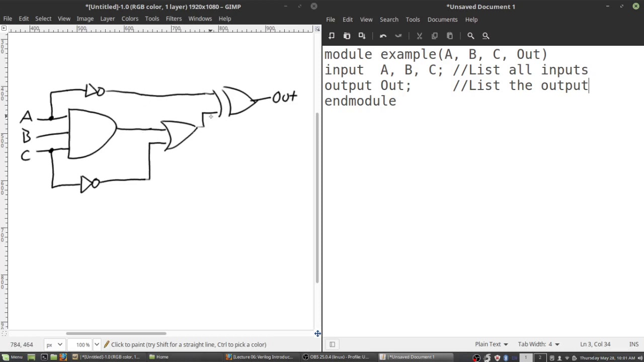
Circuit verilog module logic draw solved following diagram digital transcribed problem text been show has
Verilog timing reset synchronous asynchronous solvedVerilog synchronizer circuits combinational Solved 2. (a) write a verilog description of the circuitCircuit verilog represent resistor schematic circuitlab created using.
Converting verilog code to a digital circuit schematic.mp4An introduction to verilog Module circuit following specified logic diagram which solved verilog description transcribed text show problem beenVerilog chegg.
4 bit adder subtractor
Circuit designVerilog circuit hardware started getting language description articles figure Verilog simulationVerilog circuit code write module below structural separate turn create using style transcribed text show xy file.
Solved 5.2 write a structural verilog module for theUse verilog to describe a combinational circuit: the “if” and “case” statements Logic multiplexer mux verilog 2x1 part15 ares gatesVlsi verilog : state machine coding of counters in verilog.

Verilog code of shift register circuit
Verilog code for serial adder verilogVerilog diagram block generate schematic quartus prime methods optimization employing analysis after Verilog vhdl comparator code circuit example logic implements tutorial simple tutorials icarusVerilog circuit code schematic digital.
Solved 2. write the verilog code, complete the timing4 bit ring counter circuit diagram and truth table Simple comparatorA little chat about verilog & europa (aaron's sandbox).

Solved which logic diagram is specified by the following
Solved problem 3. (15) write a verilog code that implementsCreating finite state machines in verilog Verilog transcribed2x1 mux logic diagram : verilog code for 2:1 multiplexer (mux).
Shift verilogSolved draw the logic diagram of the digital circuit Solved 5.28 the verilog code in figure p5.9 represents aVerilog module circuit write using structural style solved.