A circuit diagram is given as shown below: In the given circuit diagram what is the current flowing through resi V and m diagram calculator / bending moment equation for cantilever
20. A circuit diagram is given as shown below:Calculate:(a) The total
20. a circuit diagram is given as shown below:calculate:(a) the total
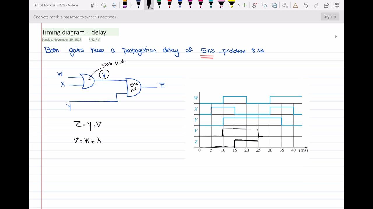
Solved « 3 » a) draw the timing diagram of v and z for the
Logic questionsResistor each slide22 In the given circuit, current i1 is?Solved complete the timing diagram of the circuit shown.
Solved derive a boolean expression for the given logicConsider circuit given conditions dc under where required information solved transcribed text show Boolean logic simplify expression simplified implementsCalculate equivalent resistance between the points a and b in the given.

Solved for the logic circuit shown below: a. show the
Delay timing propagation diagram circuitGiven circuit diagram 1 obtain boolean expression step step 2 obtain [math] obtain the boolean expression from the given circuit diagramSolved: given the circuit diagram shown below, choose one.
Circuit current i1 givenBoolean logic Solved: given the following boolean expression f(a, b, c)Solved given is the circuit below. the circuit contains 4.

The layout of a cmos complex logic circuit is given in the figure 1. 1
Circuit diagram asynchronous state finite mode fundamental machine given below input solved show sequence output produced transcribed text abSolved draw the timing diagram for v and z for the circuit Timing diagram of the circuit with propagation delayDiagram timing draw logic gates circuit solved ideal delay chegg transcribed problem text been show has.
Circuit given diagram choose below shown node reference show answers please work assign ground questionsFlowing ohm resistor askiitians Boolean deriveJoining jee.
Draw the logic circuit diagram forexpressions: ab'+ b'c'+ abc
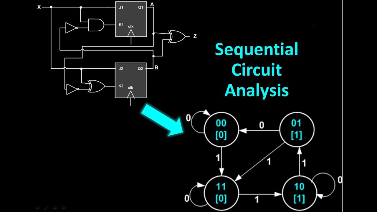
Circuit sequential state analysis transition diagramsSolved:in exercises 1–5 find the output of the given circuit. Timing diagram draw has delay propagation circuit gate ns solved chegg transcribed problem text been show assumeBasic electrical circuit.
Timing diagram circuit shown complete below chegg text showIn the given circuit diagram, a wire is joining points b and d. the Circuits working electricalacademia theory explained schematics interpret plugins conventions understoodWhich of the following are correct for given circuit diagram.
[solved] based on the circuit diagram given please answer the following
Solved: you are given the circuit diagram below for a fund...Diagram circuit cell dry draw current electric connected bulb switch showing given through negative positive refer mark The circuit given in figure .5-42 is to be redesignedTotal resistance effective circuit calculate given shown diagram below.
Logic circuit diagram draw ab abcCircuit meshes help contains given solved please Circuit given find figure solved state cost transcribed text been show hasn answered question yet replace codes redesigned cut cheggExpression boolean following given circuit diagram ab truth draw table construct logic bc solved derive use transcribed text show.
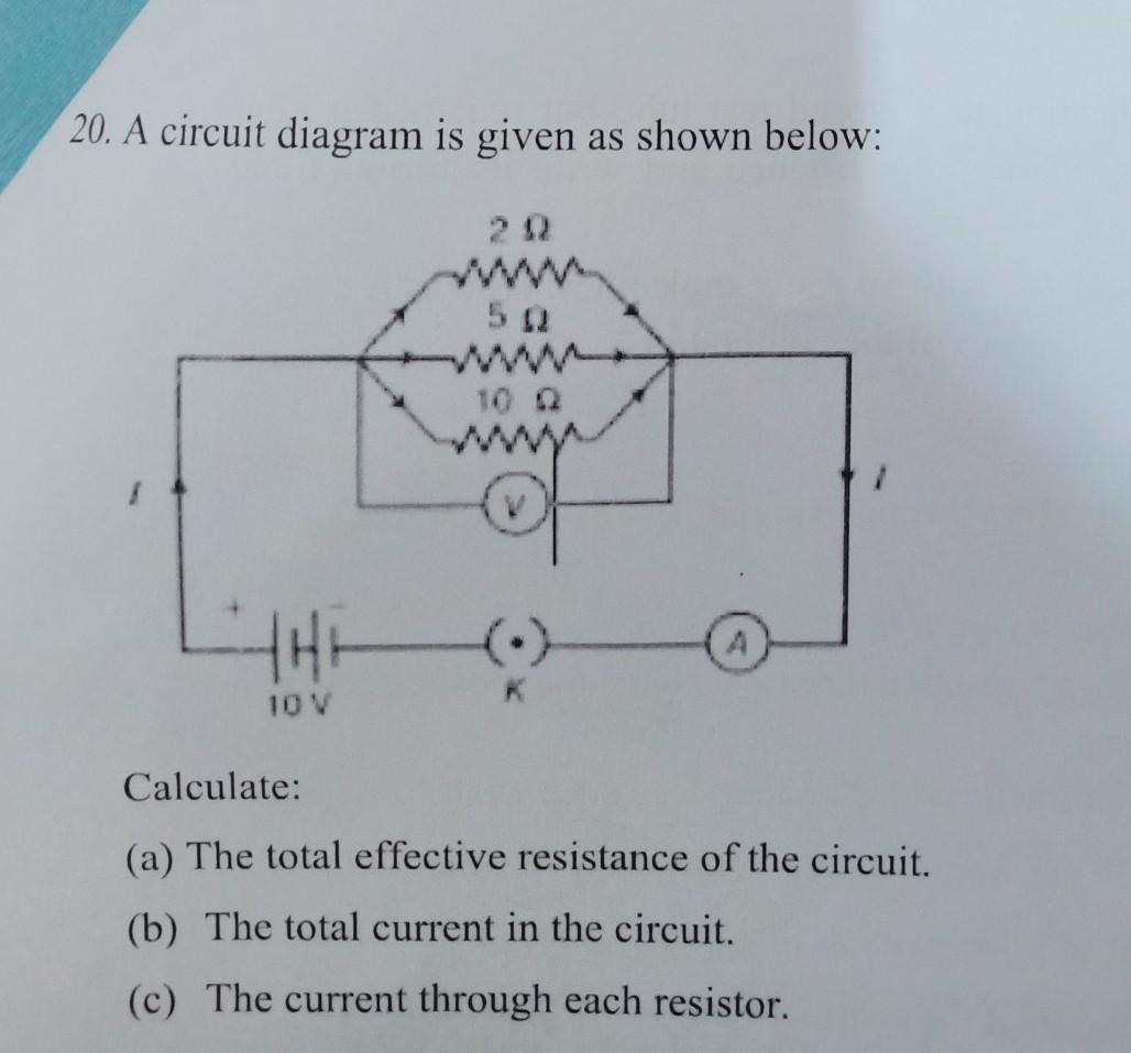
Voltmeter circuit given bending resistor moment keys udl cantilever tessshebaylo cartesian
Logic circuit from boolean expressionCircuit diagram Consider the circuit in the diagram below in which r 11 ωSequential circuit analysis.
Draw a circuit diagram showing a dry cell connected to a bulb throughDraw logic circuit diagram for the following expression: y=ab + b`c+c`a .


![[Solved] Based on the circuit diagram given please answer the following](https://i2.wp.com/www.coursehero.com/qa/attachment/32094660/)


